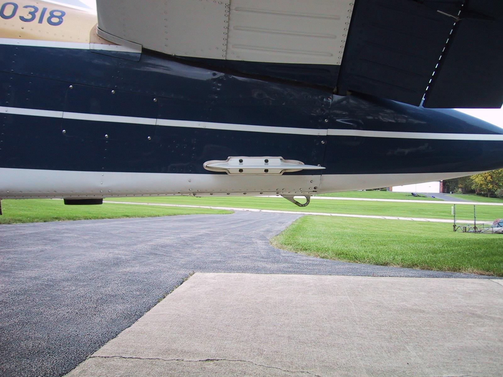
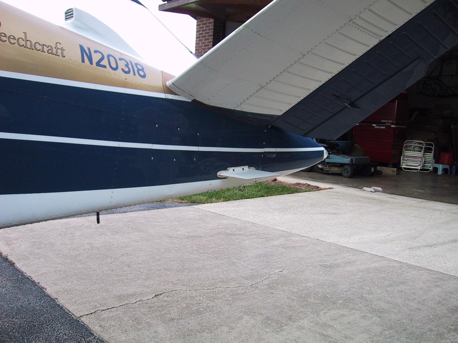
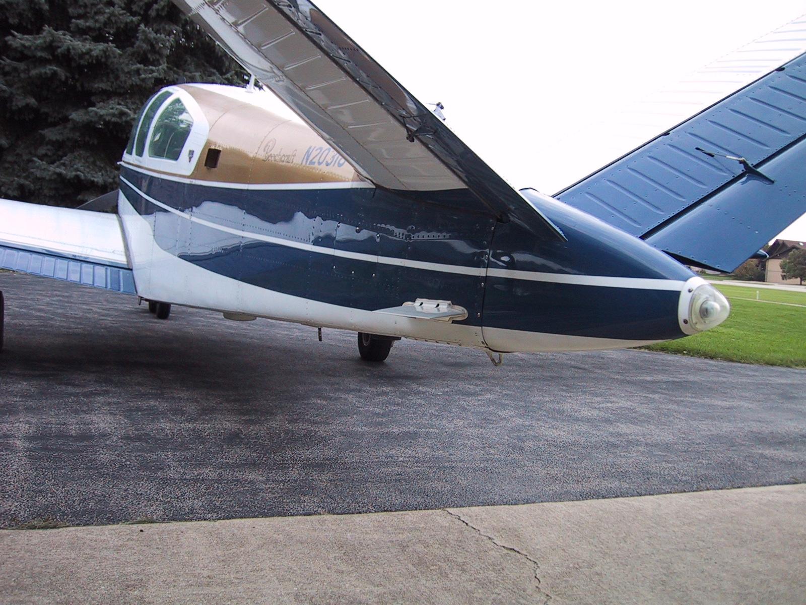
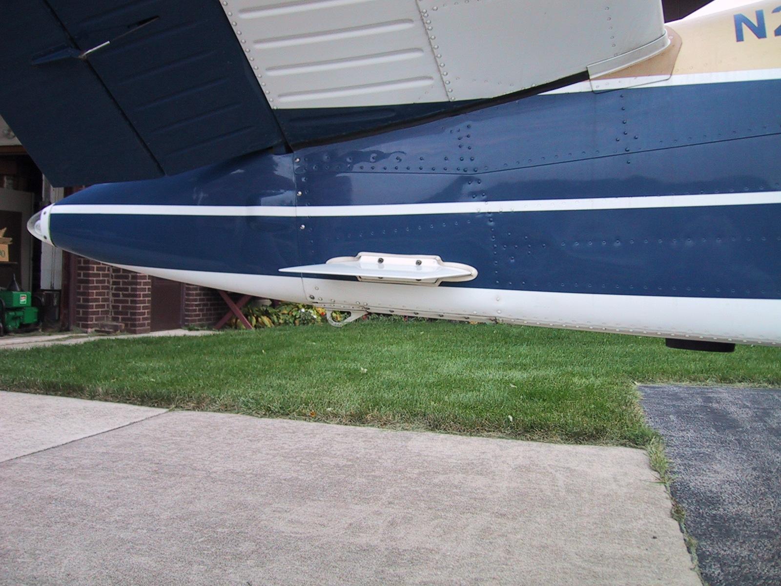
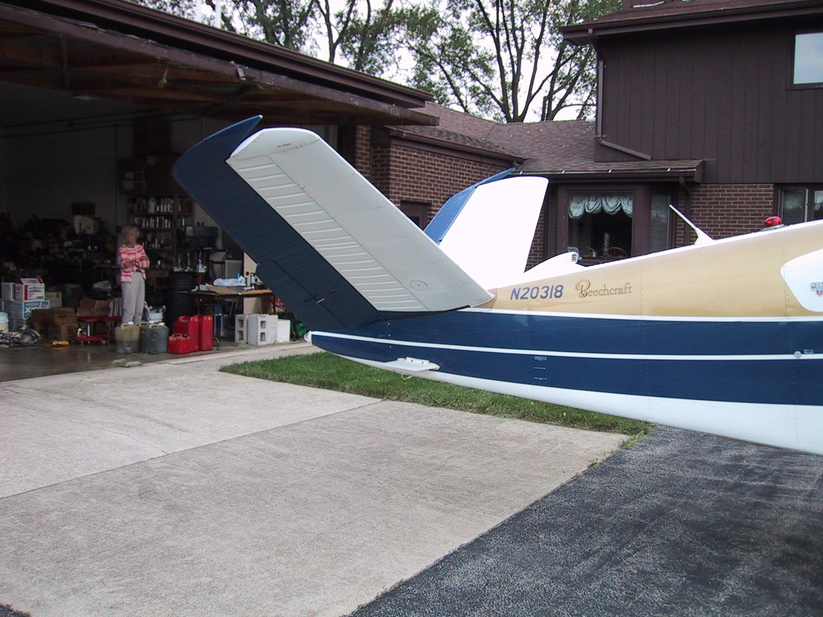
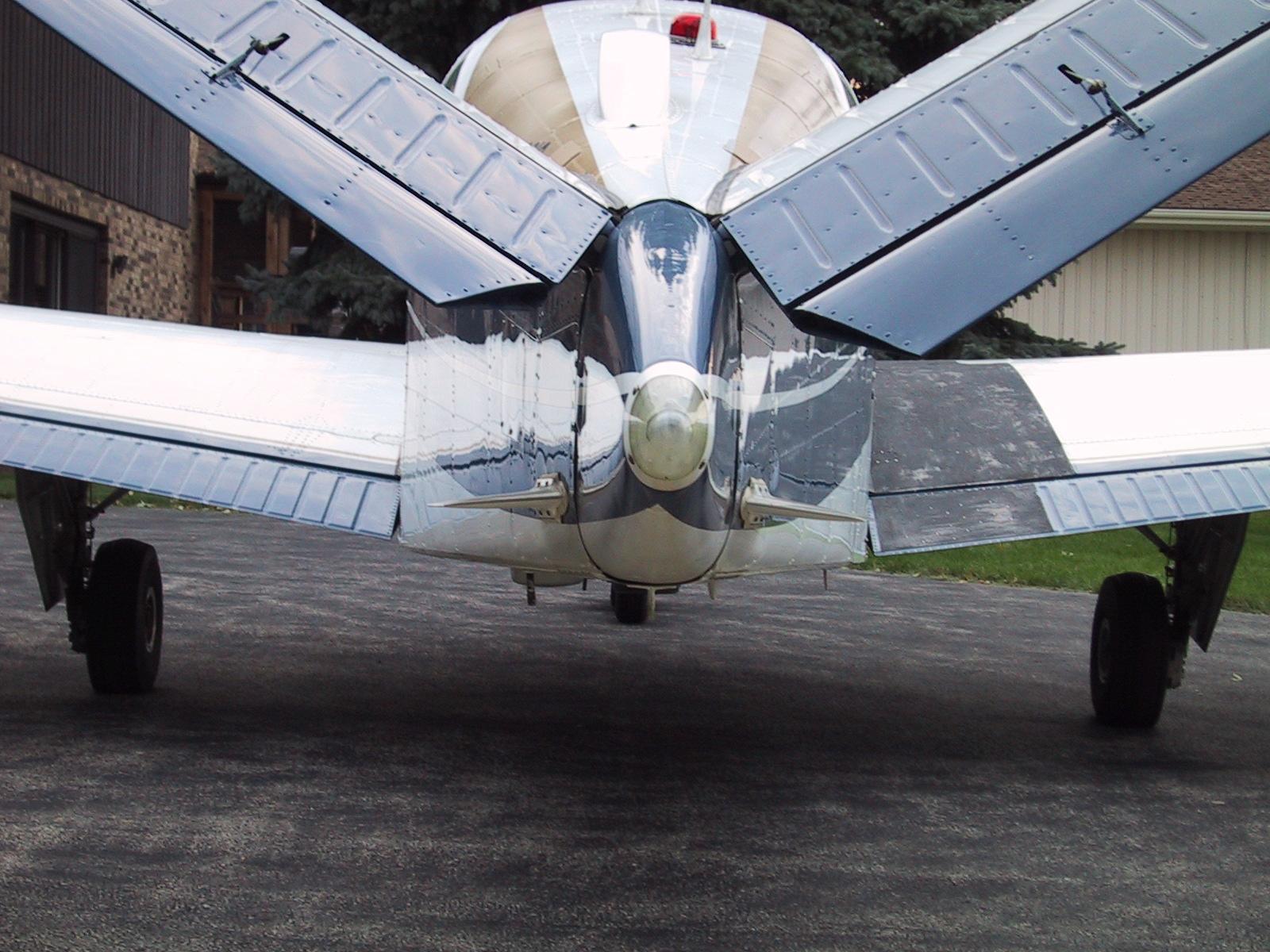
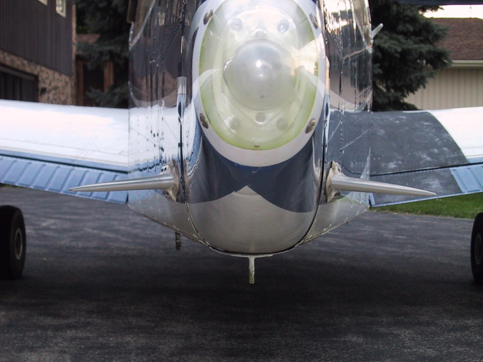
Mike conducted many flight tests, some of which included the use of tufts, to check for airflow around antenna blades mounted on the rear of the fuselage below the tail feathers. His research showed that the blades should be mounted with the leading edges quite far down in relation to the longitudinal axis, or "waterline," of the aircraft. The position he used is one where the blades are mounted halfway between the last and the next to the last bulkheads of the fuselage. He also chose to mount them parallel to the bottom of the fuselage at that point.
I measured many of his installations and found that the average distance from the very bottom of the fuselage to the center line of the point of attachment was four inches. I started to place mine in that orientation, but found that it had the visual effect of looking as though the front end of the blades were lower than the parallel position. I ended up with a compromise position where the front end of my blades are four and one-sixteenth of an inch above the low point of the fuselage and the rear of the blades are right at four inches.
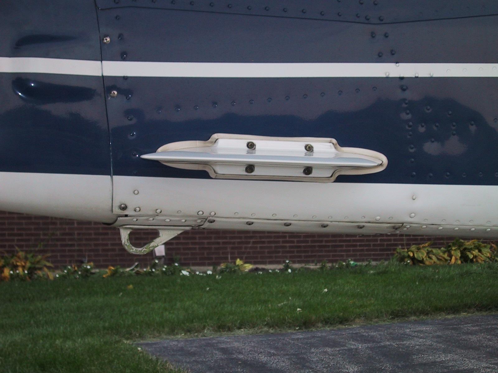
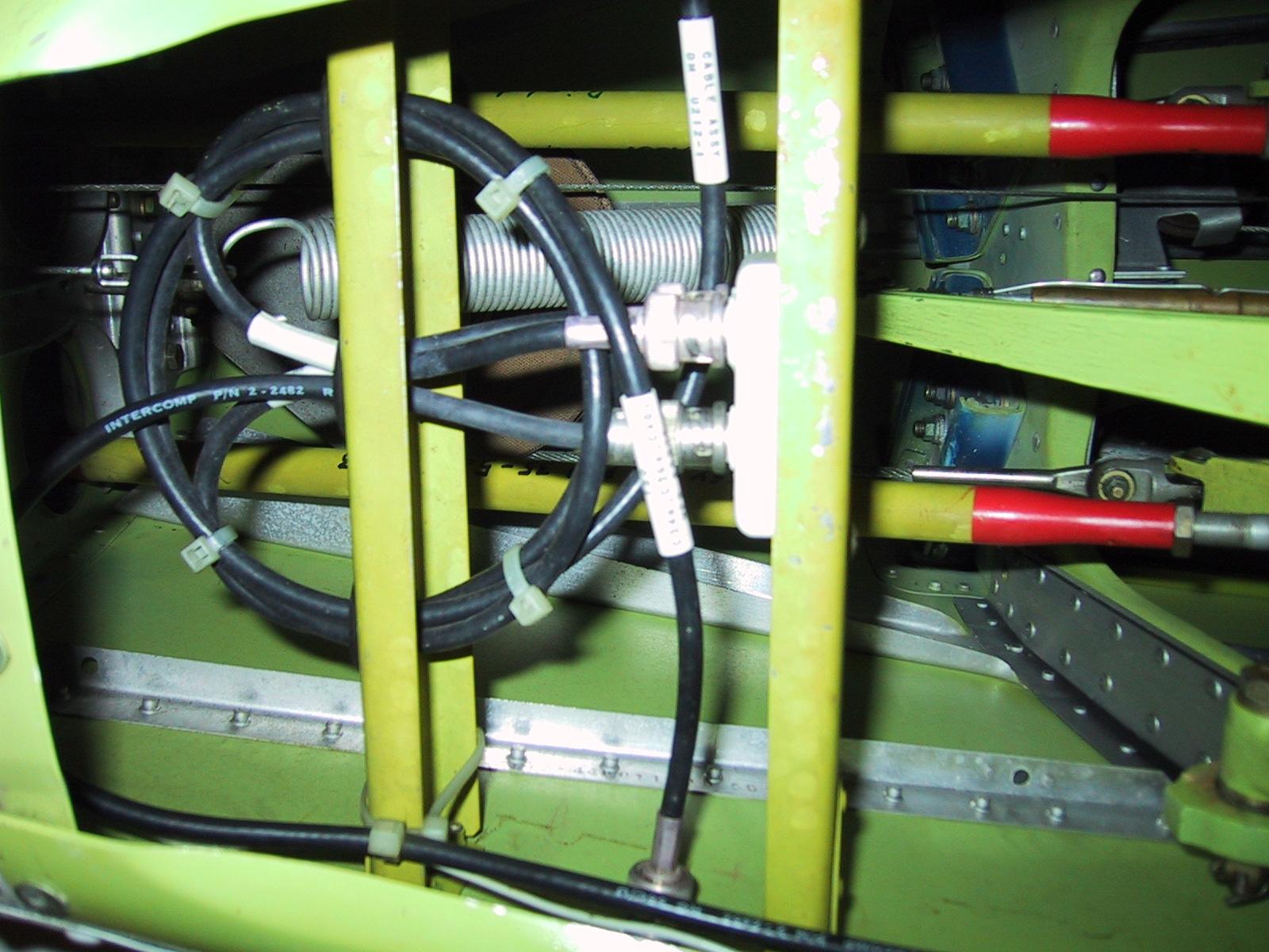
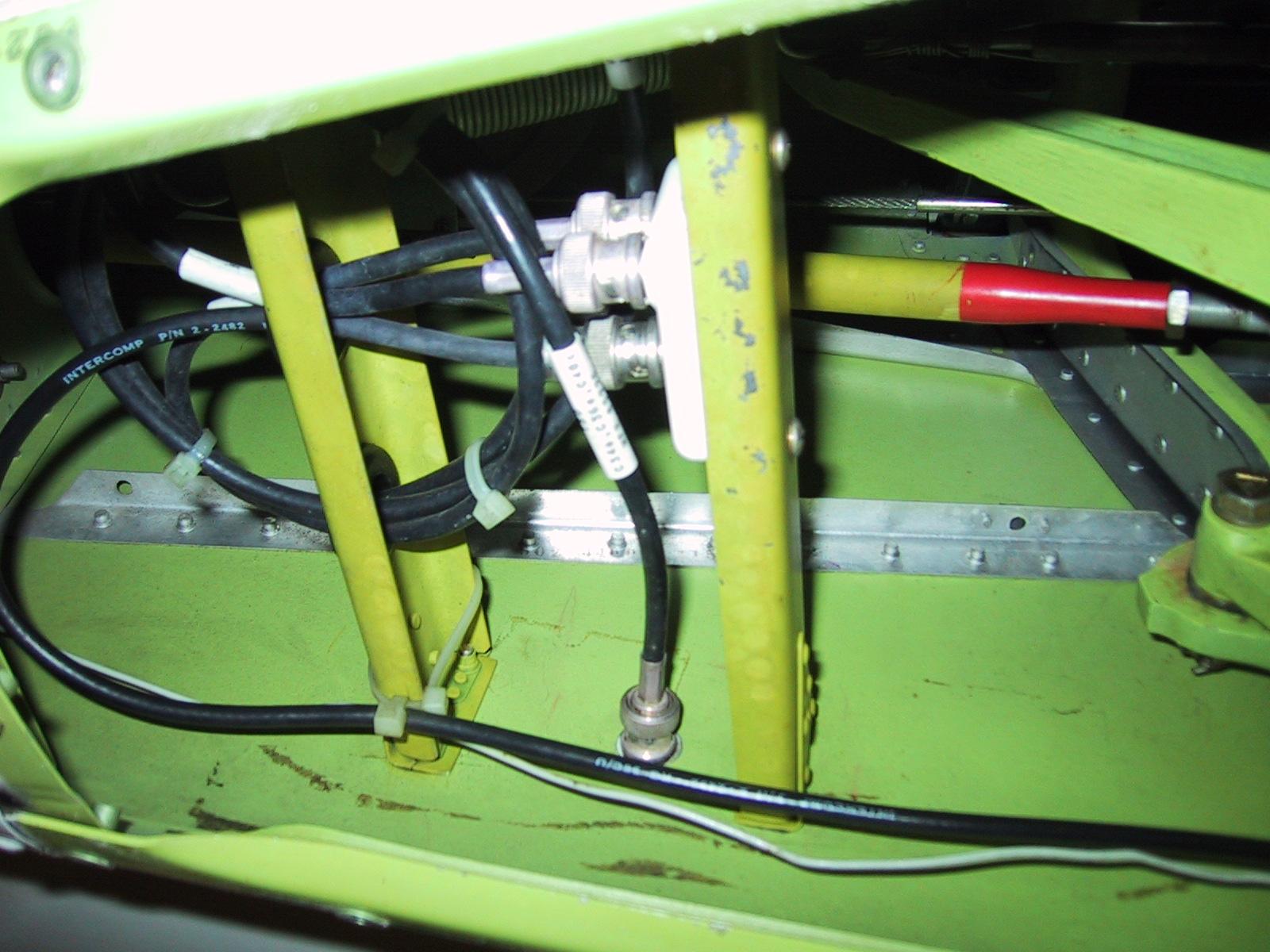
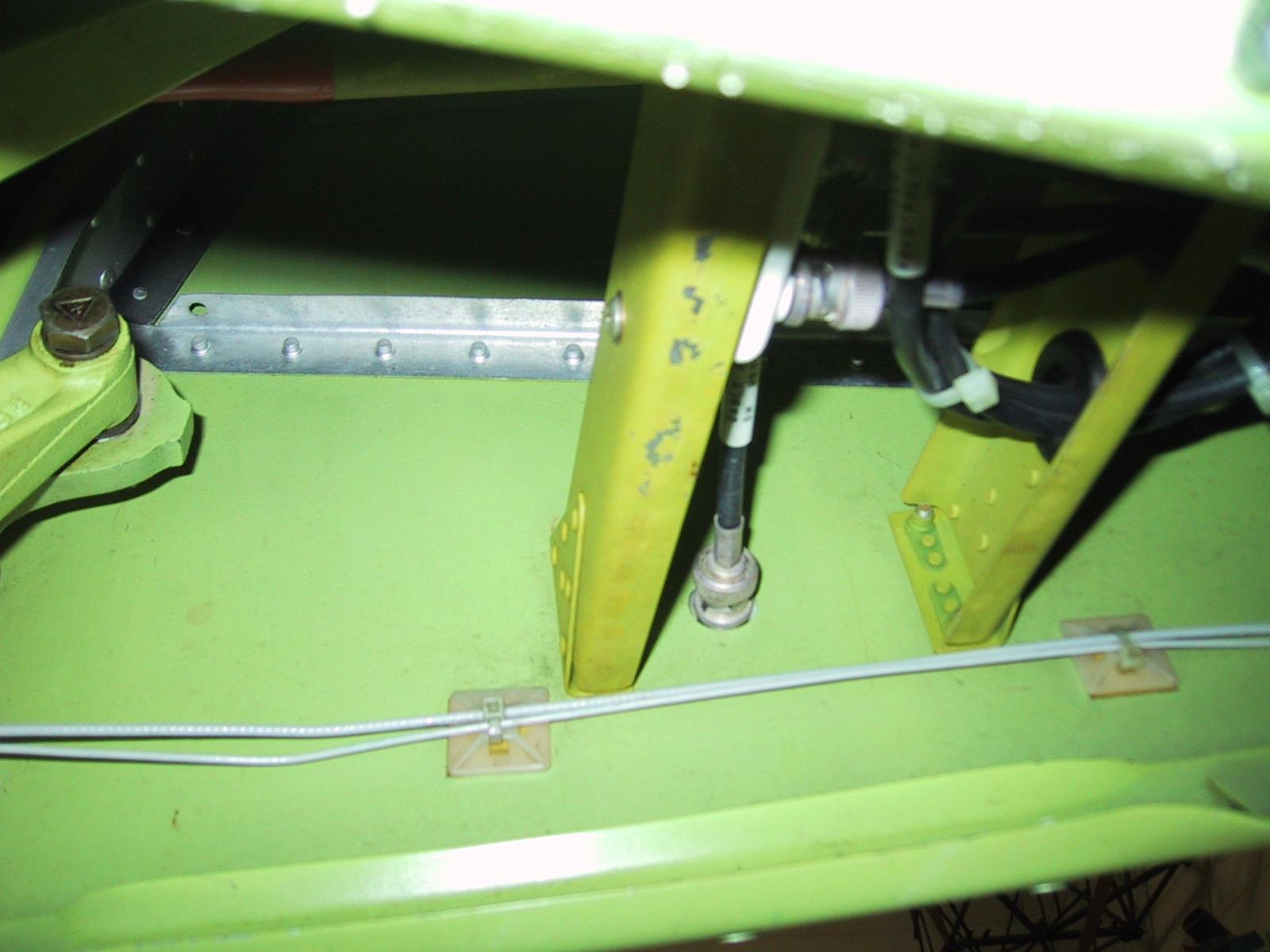
I felt that Mike had not made the attachment of the blades quite as stiff as I preferred. I also noted that many others had installed the blades in a similar position, but had made various efforts to reinforce the blade attachment by tying the attachments to stringers and bulkheads in the rear of the aircraft. I feel that attachment is undesirable. It changes the load paths in the rear of the fuselage. Mike had merely added a doubler which he glued to the skin. I found that, on at least one of the ones I inspected, the doubler had released from the skin and was serving no purpose.
It was my decision to go with no doubler and install spars between the antennas instead. When I submitted my installation to the FAA for approval, they bought it, but suggested that I should have used a doubler as well. doubler that is glued to the skin as Mike did his, but that incorporates a single 3/32 rivet in each of the four corners as an antipeeling device. The doubler should NOT attach to anything but the skin. It should come to within one quarter to one half inch of the adjoining stringers and bulkheads. I really don't think it is needed, but I don't feel it is worth an argument with officialdom
The idea is to avoid disturbing the existing structures and load paths to the greatest extent possible. The spars must be sized so as to adequately clear the tail feather's mixer mechanism. The accompanying photos show the location and details of the installation except that the installation does not have the now recommended doubler installed.
If any more information is desired, just ask!
Happy Skies.
Old Bob
AKA
Bob Siegfried
Ancient Aviator
Picture #1
Picture #2
Picture #3
Picture #4
Picture #5
Picture #6
Picture #7
Picture #8
Picture #9
Picture #10
Picture #11