The following chapter gives
an account of how a V-tail can accomplish what a conventional
tail does. The treatment is highly simplified, abstracting completely
from the following complications: (i) We ignore any effects due
to the proximity of the members of the V-tail. (ii) We leave aside
any considerations of the propwash. (iii) We don't consider the
difference in incidence of the stabilizers. Finally, we are interested
here only in the effects of pilot inputs, not gust response.
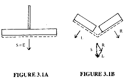
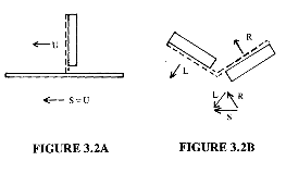
Figures 3.1A and 3.1B show control surface movements and tail forces for conventional and V-tails respectively in response to a pull on the yoke. Dashed lines represent the fixed stabilizers and solid lines represent the movable control surfaces. The view is from the rear.

With a conventional tail, only the elevators move. Their up-travel accelerates the air on the underside of the horizontal tail, reducing the pressure there and raising the pressure above the tail. The result is a down force from the tail. This is shown in Figure 3.1A by the force vector labeled S = E to denote that the sum of the forces (S) comes exclusively from the elevator (E).
When a V-tail Bonanza pilot pulls on the yoke, both ruddervators deflect as shown in Figure 3.1B. This causes the left tail member to pull down and left and the right member to pull down and right. The sum of the forces, S, is straight down, with the yaw effects from left and right ruddervators (L and R) exactly canceling. A push on the yoke works similarly.
Figures 3.2A and 3.2B show right rudder pedal inputs. In the conventional tail, the rudder moves to the right. This creates a low pressure area (or "lift") on the left side of the vertical tail, which draws the tail left or yaws the nose right about the airplane's center of gravity. The sum of the forces (S) is due to rudder (U) only.

Right rudder pedal input in
the V-tail will lower the right ruddervator and raise the left
one. The effect is an up and left force from the right tail member
and a down and left force from the left member. The sum (S) of
the left and right tail forces (L and R) has the effect of pushing
the tail left.
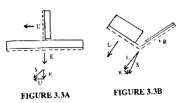
Figure 3.3A shows control surface positions and tail forces for a conventional tail when the yoke is back and the right rudder is depressed. The elevator force (E) is taildown, and the rudder force (U) is tail-left. The sum (S) of forces is tail down and left or nose up and right.

On the V-tail, the left ruddervator will be up, and the right ruddervator will be up less than the left or perhaps even down depending upon the size of the yoke and rudder displacements. Thus, the sum of the forces is, as on the conventional tail, tail-down and left or nose up and right.
The following facts from the Shop Manual for the V35B illustrate how the control mixer and ruddervator stops allow differential ruddervator displacement. With full up elevator and no rudder input, the left ruddervator will be 22 1/2 degrees up. With full right rudder and elevator neutral, the left ruddervator will be 23 degrees up. And with full up elevator and right rudder simultaneously, the left ruddervator will be 44 degrees up. By contrast, the elevator of the A36 is limited to 23 degrees up and 20 degrees down, while the rudder is limited to 25 degrees left or right.
From "Flying the Beech Bonanza", Eckalbar, John C., McCormick-Armstrong Co, Incorporated, 1986, ISBN 0-911978-03-8. Used by permission.